Editing Screen Settings

Contents
>> |
To edit the screen settings which are currently in use |
Select the “Screen Color Scheme and Font…“ item from the “Options“ menu.
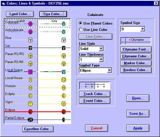
This will display the “Colors, Lines & Symbols” dialog box from which any of the settings may be edited.
You may edit any of the following items.
• |
Land Color – This color is used to fill in all areas of land. Click on the Land Color... button and choose one of the available colors from the “Color Selection” dialog. See Making Color Selections. |
• |
Sea Color - This color is used to fill in all areas of sea and lakes. Click on the Sea Color... button and choose one of the available colors from the “Color Selection” dialog. See Making Color Selections. |
• |
Coastline Color – This color is used to draw the outline of the landmasses and lakes. Click on the Coastline Color... button and choose one of the available colors from the “Color Selection” dialog. See Making Color Selections. Note that the coastline color cannot be the same as the land color, although it can be the same as the sea color. |
• |
Symbol Size – This affects the size of the planet glyphs around the edge of the map area. Select an entry from the drop-down list box of available symbol sizes. |
• |
Cityname Font – This affects the font used to write any city and country names onto the map. Click on the Cityname Font… button and choose a font name, style and size. |
• |
Cityname Color – This color is used for city and country names drawn onto the map. Click on the Cityname Color... button and choose one of the available colors from the “Color Selection” dialog. See Making Color Selections. |
• |
City Marker Color – This color is used for the crosshairs marking the location of any cities drawn onto the map. Click on the Marker Color... button and choose one of the available colors from the “Color Selection” dialog. See Making Color Selections. |
• |
Borders Color – This color is used for any internal state or country borders on the map. Click on the Borders Color... button and choose one of the available colors from the “Color Selection” dialog. See Making Color Selections. |
• |
Track Color – This color is used for any user-defined tracks drawn onto the map. Click on the Track Color... button and choose one of the available colors from the “Color Selection” dialog. See Making Color Selections. Note that this color applies only to user-defined tracks, as UniSys Hurricane tracks are always drawn using a pre-set color scheme devised by UniSys. See UniSys Hurricanes. |
• |
Event Marker Color - This color is used for any events drawn onto the map, and for the expanding/contracting highlight circle which is used to show a single event location or track start location. Click on the Event Color... button and choose one of the available colors from the “Color Selection” dialog. See Making Color Selections. |
• |
Line Attributes - First click on the line type in the display area. This will highlight that line type by surrounding it with a black and white focus rectangle, and enter the line type name into the caption box on the top right of the screen.. Then select the required line attributes from the following. |
• |
Use Planet Colors/Use Line Color - This enables you to choose whether to display this line type using the color of whichever planet which is associated with the line (ie. different for every line), or whether to always use the same line color, regardless of which planet is associated with it. |
• |
Line Color - Clicking on this button enables you to choose one of the available colors from the “Color Selection” dialog. See Making Color Selections. This color is only used if the Use Line Color option has been selected. |
• |
Line Style - You can select one of the available styles from the drop-down list box. However, note that if you choose a line thickness greater than 1, then the line style will be drawn as SOLID, regardless of which line style setting you choose. |
• |
Line Thickness - You can select one of the available line thicknesses from the drop-down list box. However, note that if you choose a line thickness greater than 1, then the line style will be drawn as SOLID, regardless of which line style setting you choose. |
• |
Symbol Type - You can select one of the available symbol shapes from the drop-down list box. |
Note that each time you alter any setting, the display area is immediately updated to reflect the changes that you have made, showing you what the new settings will look like on the maps.
The purpose of all these settings is to help you to see which astrological lines are which when they are displayed on the map. For example, you might choose to have the MC lines use the planet colors, because the MC lines are always vertical lines of longitude on a rectangular map, so you can easily identify them. However, rising and setting lines for a planet run together cannot be easily differentiated, so you might choose to switch to the line color option for both of these line types and have all the rising lines one color, and all the setting lines another color.
When you first use Solar Maps, you will find that various settings have been chosen to help the typical user recognise the different line types quickly and easily. However, it is up to you to decide whether you would prefer to personalise these settings for your own taste and requirements.
After you have edited the settings and clicked on the OK button, any changes that you have made will take effect immediately on the currently displayed map. These changes will be used either until you edit the settings again, or until you exit from Solar Maps.
Important Note: Any changes that you make to the settings will not be retained for future sessions with Solar Maps unless you use the “Save Settings“ option to permanently save them to a file.